Basics of Multi-Zone Computations
SU2 is capable of solving physical problems in distinct zones coupled through interfaces. Applications range from Fluid-Fluid coupling (e.g. using a sliding mesh approach) over Conjugate-Heat-Transfer to Fluid-Structure Interactions problems. The following section gives an overview on the general terminology for multizone computations and how you can make use of these features. For specific problem-related options, please refer to the Tutorials.
What is a Zone ?
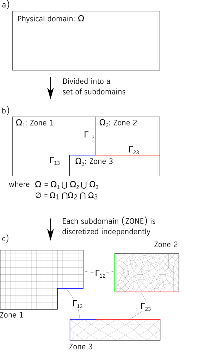
We refer to a Zone as a subdomain in your physical problem. For example consider a heated cylinder immersed into a fluid. In this case, the solid cylinder would be refered to as zone 0 and the fluid domain as zone 1. All zones can be discretized independently and do not need to be matching at the interfaces. See the figure below.
Multi-zone and Multi-physics
A multi-zone problem is a problem that consists of multiple zones. If there are additionally different physical problems solved in the individual zones (i.e. the option SOLVER is different) then we refer to that as a multi-physics problem, otherwise we call it a single-physics problem. In that sense, every multi-physics problem is also a multi-zone problem. However, both cases differ slighty in how a problem is set up using the config files.
How to set up a single-physics problem
To enable the multi-zone mode use the option MULTIZONE = YES (default is NO). If all zones share all config options and are not connected, this is all you have to do. To define a common interface between zones use the option MARKER_ZONE_INTERFACE. This option should be set to a list of markers, in which every two consecutive markers are considered as a connected pair, e.g.:
MARKER_ZONE_INTERFACE= ( internal_interface, inner_interface, domain_interface, external_interface )
In this example internal_interface, inner_interface and domain_interface, external_interface are connected. The type of interface is determined automatically, depending on the type of the physical problem (set with SOLVER).
Note: Currently the only single-physics problems available are Fluid-Fluid cases (that means SOLVER must be set to EULER/INC_EULER, NAVIER_STOKES/INC_NAVIER_STOKES or RANS/INC_RANS).
Sub-config files
Even if you run a single-physics problem, there might be cases where you want to use different config options in the individual zones. For example to specify a rotation in one zone or to use a different numerical scheme. This can be accomplished using the sub-config file feature of SU2. A sub-config file is similar to the usual config file, but only contains options which are different from the main config file in the particular zone. This allows to override or to only set options in certain zones. To use this feature just provide a list of sub-config files using the CONFIG_LIST option. The number of items in that list must match the number of zones (of course you can provide an empty file or the same file for multiple zones). The first item in that list sets options in zone 0, the second in zone 1 and so on.
As an example consider a problem with two zones coupled using a Fluid-Fluid interface. In the second zone we want to add a rotation. The two additional entries in the main config file are the following:
% Enable Multizone mode
MULTIZONE= YES
%
% List of config files to specify zone options
CONFIG_LIST= (zone_0.cfg, zone_1.cfg)
%
In zone 0 we do not want to override any options from the main config. In particular (in contrast to zone 1) we do not want to add rotation. The file zone_0.cfg could be very well just empty, but to make it more clear we explicitly disable any grid movement:
% zone_0.cfg
% ----------------------- DYNAMIC MESH DEFINITION -----------------------------%
%
% Dynamic mesh simulation (NO, YES)
GRID_MOVEMENT= NONE
%
zone_1.cfg contains the options to set the rotation:
% zone_1.cfg
% ----------------------- DYNAMIC MESH DEFINITION -----------------------------%
%
% Type of dynamic mesh (NONE, ROTATING_FRAME)
GRID_MOVEMENT= RIGID_MOTION
%
% Motion mach number (non-dimensional). Used for intitializing a viscous flow
% with the Reynolds number and for computing force coeffs. with dynamic meshes.
MACH_MOTION= 0.35
%

MOTION_ORIGIN= 0.3 0.0 0.0

% Angular velocity vector (rad/s) about the motion origin.
ROTATION_RATE = 0.0 0.0 160.0
How to set up a multi-physics problem
While for the single-physics problems the usage of sub-config files is optional, setting up a multi-physics problem heavily relies on this feature. A good way to start is to first create a separate config file for each individual zone. If it is possible, also try to run each zone independently (with appropriate boundary conditions) to find proper numerical settings. To couple the zones create a new config file with the option MATH_PROBLEM set to MULTIPHYSICS. Then specify the list of config files with CONFIG_LIST. These two options are mandatory. To set a coupling between the zones the MARKER_ZONE_INTERFACE option can be used (same way as for the single-physics problem). As an example consider the following main config file:
% main_config.cfg
% ------------------------ MULTI-PHYSICS SETUP --------------------------------%
% Problem definition
PHYSICAL_PROBLEM= MULTIPHYSICS

% The list of config files
CONFIG_LIST = (configFlow.cfg, configSolid.cfg)

% The markers which should be coupled
MARKER_ZONE_INTERFACE= (PIN, PINSD)
The files configFlow.cfg and configSolid.cfg contain a full set of options to run a flow or a heat equation problem, respectively (apart from a definition of the boundary conditions for the markers PIN and PINSD, which will be determined automatically). However, every option not present in the sub-config files will be inherited from the main config file. If it is also not set there, then the default value will be used. This means options common in all zones, can be written to the main config file.
Providing mesh information for a multi-zone problem
For a multizone problem you have two options to provide the mesh (set with the option MULTIZONE_MESH).
- Multi-zone mesh (
MULTIZONE_MESH= YES(default)): In this case the mesh information for all zones is in one file. Note that this option currently only works with the native SU2 mesh format (MESH_FORMAT= SU2) and the keywordsNZONE=andIZONE=have to be present in the mesh file. Example:
% Number of zones
NZONE= 2


% Information for zone with index 1 follows
IZONE= 1
%
% Problem dimension
%
NDIME= 2
%
% Inner element connectivity
NELEM= 39092
 5  1264 1265  825    0
...

% Information for zone with index 2 follows
IZONE= 2
%
% Problem dimension
%
NDIME= 2
%
% Inner element connectivity
%
NELEM= 6365
 5   364  365  366    0
...
- Single-zone mesh (
MULTIZONE_MESH= NO): In this case there is a separate mesh file for each zone andMESH_FILENAMEmust be set in the sub-config files.