Mesh File
This page only applies to SU2 version 6.2.0 and lower.The new documentation section can be found here.
SU2 mainly uses a native mesh file format as input into the various suite components. Limited support for the CGNS data format has also been included as an input mesh format. CGNS support can be useful when it is necessary to create complex geometries in a third-party mesh generation package that can export CGNS files. A converter from CGNS to the native format is also built into SU2. Details on how to create and use these mesh formats is given below.
SU2 Native Format (.su2)
In keeping with the open-source nature of the project, SU2 relies mostly on its own native mesh format. The format is meant to be simple and readable. A description of the mesh and some examples are below.
Description
The SU2 mesh format carries an extension of .su2, and the files are in a readable ASCII format. As an unstructured code, SU2 requires information about both the node locations as well as their connectivity. The connectivity description provides information about the types of elements (triangle, rectangle, tetrahedron, hexahedral, etc.) that make up the volumes in the mesh and also which nodes make up each of those elements. Lastly, the boundaries of the mesh, or markers, are given names, or tags, and their connectivity is specified in a similar manner as the interior nodes.
Specification
Consider the following simple, 2D mesh for a square domain consisting of 8 triangular elements. It will be used to explain the .su2 mesh format.
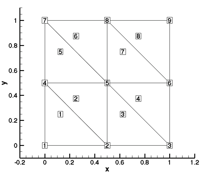
Square Mesh Example: Note that the figure uses Tecplot node and element number (1-based). The node and element numbering for SU2 start at 0.
The first line of the .su2 mesh declares the dimensionality of the problem. SU2 can handle 2D or 3D geometries. As a note, for 2D simulations, it is recommended that a truly 2D mesh is used (no z-coordinates) rather than a quasi-2D mesh (one or more cells deep in the third dimension with symmetry boundary conditions). For the 2D square mesh, the dimension is defined as follows:
NDIME= 2
SU2 searches specifically for the keyword NDIME= in order to set the dimension, and the dimension value will be stored for use throughout the code. This value would be 3 for a 3D mesh. Note that while “%” is used here to denote comments, SU2 does not officially recognize it as such. Extra text added to the mesh file between sections (such as lines following a “%”) will simply be ignored.
To specify the point list, SU2 first searches for the string NPOIN= and stores the total number of nodes in the mesh. This value is given first, as it is used to set up a loop over all of the grid points that must immediately follow this line. Then, the coordinates for each of the nodes are given. This is specified in the .su2 format as:
NPOIN= 9
0.00000000000000 0.00000000000000
0.50000000000000 0.00000000000000
1.00000000000000 0.00000000000000
0.00000000000000 0.50000000000000
0.50000000000000 0.50000000000000
1.00000000000000 0.50000000000000
0.00000000000000 1.00000000000000
0.50000000000000 1.00000000000000
1.00000000000000 1.00000000000000
In this case, there are 9 nodes in the 3x3 square above. Immediately after the node number specification comes the list of node coordinates in cartesian space. Each line gives the coordinates for a single grid vertex. The grid points are assigned a global element index of 0 through 8 in the order they appear in the file. This global element index is implied by the ordering and does not need to be explicitly specified by the file, although some legacy meshes may still contain an explicit index at the end of the line that can be ignored.
For a 2D mesh, only x and y coordinates are required, but a 3D mesh would give x, y, and z coordinates. Note that the global index values for the nodes and elements stored within SU2 are zero-based, as opposed to starting from 1 as Tecplot does. The location of each node in the list can be confirmed in space by adding 1 to the implied global index from the ordering and comparing with the figure above.
The next part of the file describes the interior element connectivity, which begins with the NELEM= keyword:
NELEM= 8
5 0 1 3
5 1 4 3
5 1 2 4
5 2 5 4
5 3 4 6
5 4 7 6
5 4 5 7
5 5 8 7
SU2 is based on unstructured mesh technology, and thus supports several element types for both 2D and 3D elements. Unlike for structured meshes where a logical, ordered indexing can be assumed for neighboring nodes and their corresponding cells (quadrilaterals in 2D and hexahedral elements in 3D), for an unstructured mesh, a list of nodes that make up each element, or the connectivity as it is often called, must be provided. First, SU2 will search for the string NELEM= and then store the number of interior elements. This value is given first, as it is used to set up a loop over all of the elements which must immediately follow this line. For the square mesh above, this corresponds to the 8 triangular interior elements that are assigned a global element index of 0 through 7 in the order they appear in the file. This global element index is implied by the ordering and does not need to be explicitly specified by the file, although some legacy meshes may still contain an explicit index at the end of the line that can be ignored.
Each following line describes the connectivity of a single element. The first integer on each line is a unique identifier for the type of element that is described. SU2 supports line, triangle, quadrilateral, tetrahedral, pyramid, prism, and hexahedral elements. The identifiers follow the VTK format:
| Element Type | Identifier |
|---|---|
| Line | 3 |
| Triangle | 5 |
| Quadrilateral | 9 |
| Tetrahedral | 10 |
| Hexahedral | 12 |
| Prism | 13 |
| Pyramid | 14 |
In our square mesh, all elements are triangles, and thus the identifier (first integer) on all lines is 5. Following the identifier is a list of the node indices that make up the element. Each triangular element will have 3 nodes specified, a rectangular element would have 4 nodes specified, a tetrahedral element would have 4 nodes specified, and so on. Note again that the global index values for the nodes and elements stored within SU2 are zero-based, as opposed to starting from 1 as Tecplot does, which was used to create the mesh image. For example, take the triangular element described in the first line, which would be indexed as 0 in SU2 (1 in Tecplot). The SU2 nodes are given as (0,1,3) which would correspond to (1,2,4) in Tecplot. Looking at the figure of the mesh above, we see that this is the lower left triangular element. The ordering of the nodes given in the connectivity list for a specific element is important, and the user is referred to the VTK format guide for the correct ordering for each supported element type (page 9).
The final component of the mesh is a description of all boundaries (which we call markers), including a name (what we call a tag). For each boundary, the connectivity information is specified using the same node global index values given above. For a 2D mesh, only line elements are supported along the boundaries. For a 3D mesh, triangular and quadrilateral elements are the possible options for boundary elements. This section of the .su2 mesh file appears as:
NMARK= 4
MARKER_TAG= lower
MARKER_ELEMS= 2
3 0 1
3 1 2
MARKER_TAG= right
MARKER_ELEMS= 2
3 2 5
3 5 8
MARKER_TAG= upper
MARKER_ELEMS= 2
3 8 7
3 7 6
MARKER_TAG= left
MARKER_ELEMS= 2
3 6 3
3 3 0
First, the number of boundaries, or markers, is specified using the “NMARK=” string. Then for each marker, a name, or tag, is specified using “MARKER_TAG=.” This tag can be any string name, and the tag name is used in the configuration file for the solver when specifying boundary conditions. Here, the tags “lower,” “right,” “upper,” and “left” would be used. The number of elements on each marker, using “MARKER_ELEMS=,” must then be specified before listing the connectivity information as is done for the interior mesh elements at the start of the file. Again, the unique VTK identifier is given at the start of each line followed by the node list for that element. For our example, only line elements (identifier 3) exist along the markers, and on each boundary of the square there are 2 edges of a triangle that make up the marker. These elements can again be verified with the mesh figure above.
Examples
Attached here is the simple square mesh from above in .su2 format, along with codes for creating this file in the Python, C++, and Fortran 90 programming languages. These scripts are meant to be examples of how to write .su2 meshes in a few common languages which can be easily modified for creating new meshes:
- Square mesh: square.su2
- Python square mesh generator: square.py
- C++ square mesh generator: square.cpp
- Fortran 90 square mesh generator: square.f90
CGNS Format
To make creating your own meshes easier and more accessible, support for the open CGNS data standard has been included within SU2. The main advantage gained is that complex meshes created in a third-party software package (one that supports unstructured, single-zone CGNS file export) can be used directly within SU2 without the need for conversion to the native format. Moreover, as CGNS is a binary format, the size of the mesh files can be significantly reduced. If needed, a converter from CGNS to the SU2 format has been built into SU2 (See the inviscid wedge tutorial).
Compiling with CGNS Support
Starting with SU2 v4.3, the source for version 3.3.0 of the CGNS library is shipped with SU2 in the externals/ directory, and it is automatically built and linked for you when compiling SU2 (ADF support only).
Using and Converting CGNS Meshes
In order to use a CGNS mesh (assuming the CGNS library has been installed and SU2 successfully compiled), the user simply needs to specify the input mesh format to be “CGNS” in the configuration file for their simulation. The configuration file option is “MESH_FORMAT=” and appears as:
MESH_FORMAT= CGNS
It is important to note that SU2 will not use any specific boundary conditions that are embedded within the CGNS mesh. However, it will use the names given to each boundary as the marker tags. These marker tags are used to set the boundary conditions in the configuration file. Therefore, it is recommended that the user give names to each boundary in their mesh generation package before exporting to CGNS. If you do not know the number of markers or their tags within a CGNS file, you can simply attempt a simulation in SU2_CFD (leaving out the boundary information in the configuration file at first), and during the preprocessing stage, SU2 will read and print the names of all boundary markers to the console along with other grid information before throwing an error due to incomplete boundary definitions. The user can then incorporate these marker tags into the configuration file with the appropriate boundary conditions.
Third-Party Mesh Software
We are continuously working to integrate SU2 with industry-standard tools. We currently have an output plugin for the Pointwise(R) meshing software. This custom addition allows users of Pointwise version 17.00 and later to directly output their meshes in the native SU2 format. The plugin is available natively within recent versions of Pointwise (V17.0R2 or later).
In addition, a number of other packages support direct output to the SU2 format, such as GMSH and CENTAUR. CGNS files created by a number of other meshing packages have been successfully tested and used, such as those from ICEM CFD, for instance.