-
Inviscid Bump in a Channel
Inviscid Supersonic Wedge
Inviscid ONERA M6
Laminar Flat Plate
Laminar Cylinder
Turbulent Flat Plate
Transitional Flat Plate
Transitional Flat Plate for T3A and T3A-
Turbulent ONERA M6
Unsteady NACA0012
Epistemic Uncertainty Quantification of RANS predictions of NACA 0012 airfoil
Non-ideal compressible flow in a supersonic nozzle
Non-ideal compressible flows with physics-informed neural networks
Aachen turbine stage with Mixing-plane
-
Inviscid Hydrofoil
Laminar Flat Plate with Heat Transfer
Turbulent Flat Plate
Turbulent NACA 0012
Laminar Backward-facing Step
Laminar Buoyancy-driven Cavity
Streamwise Periodic Flow
Species Transport
Composition-Dependent model for Species Transport equations
Unsteady von Karman vortex shedding
Turbulent Bend with wall functions
Wind velocity and pollutant dispersion in a city
-
Static Fluid-Structure Interaction (FSI)
Dynamic Fluid-Structure Interaction (FSI) using the Python wrapper and a Nastran structural model
Static Conjugate Heat Transfer (CHT)
Unsteady Conjugate Heat Transfer
Solid-to-Solid Conjugate Heat Transfer with Contact Resistance
Incompressible, Laminar counterflow diffusion flame
Incompressible, Laminar Combustion Simulation
User Defined combustion model with Python
-
Unconstrained shape design of a transonic inviscid airfoil at a cte. AoA
Constrained shape design of a transonic turbulent airfoil at a cte. CL
Constrained shape design of a transonic inviscid wing at a cte. CL
Shape Design With Multiple Objectives and Penalty Functions
Unsteady Shape Optimization NACA0012
Unconstrained shape design of a two way mixing channel
Adjoint design optimization of a turbulent 3D pipe bend
Unconstrained shape design of a two way mixing channel
| Written by | for Version | Revised by | Revision date | Revised version |
|---|---|---|---|---|
| @TobiKattmann | 7.2.1 | @ |
Solver: |
|
Uses: |
|
Prerequisites: |
Species Transport |
Complexity: |
Advanced |
Disclaimer
This Tutorial builds directly on the case given as Prerequisite on the top of the site link. Therefore details to the problem setup, mesh, etc. are not repeated here. However the process outlined in this tutorial is directly applicable to many other cases using SU2.
Instead of the python tools for finite differences or shape optimization that are part of SU2 directly, the standalone python tool FADO is used. Please follow the information on the given github repo in order to use FADO.
Goals
This tutorial is a rather extensive guide covering the following steps, assuming a converging primal case is present:
- Validation of perfect restarts as a basis for the Discrete Adjoint solver (this is done using a separate bash-script). This section focuses on code development aspects, and may be skipped by general users.
- Setting up an FFD-box and writing it to the mesh
- Manual testing of the mesh deformation
- Gradient validation using FADO
- Shape optimization using FADO
Following these steps proved to be especially useful when developing new features as each step is an incremental rise in complexity and is much easier to debug, compared starting right away with an optimization that then fails to provide satisfactory results.
Resources
You can find the resources for this tutorial in the folder incompressible_flow/Inc_Species_Transport and the respective subfolders.
1. Restart Validation
The script restart_validation.sh performs 4 simulations using species3_venturiPrimitive.cfg to check whether primal and primal-adjoint restarts work. This script is best used with HISTORY_OUTPUT= RMS_RES as then the output comparison is the most straight forward. The SU2 binary is deduced from the environmental variable SU2_RUN, so make sure that is set correctly. With the explanation given here and the comments in the script it should be straight forward adaptable to other cases.
- Primal simulation with n+1 timesteps. This is the ground truth of the expected residual values. Takes Residuals from the
historyfile. - Primal simulation with n timesteps. We will restart steps 3. and 4. from this simulation.
- Primal simulation with 1 timestep, restarted from simulation in 2nd step. Takes Residuals from the
historyfile. - Adjoint simulation with 1 timestep, using the primal restart file from simulation in 2nd step. The primal residuals that are printed in the screen output are taken for comparison.
When using the recommended HISTORY_OUTPUT= RMS_RES the output should provide the following:
-5.010542647 -4.537626591 -4.207538398 0.4686163065 -6.594021422 0.4978738082 -5.253262361 -5.467591972
-5.010542647 -4.537626591 -4.207538398 0.4686163065 -6.594021422 0.4978738082 -5.253262361 -5.467591972
-5.010542647 -4.537626591 -4.207538398 0.4686163065 -6.594021422 0.4978738082 -5.253262361 -5.467591972
Where in each row the residual of each equation is listed (P, vx, vy, T, k, w, Species_0, Species_1). The primal restart (2nd row) and the adjoint primal restart (3rd row) provide identical results compared to the ‘full’ primal simulation (1st row). Small deviations in the last digits are not an issue, especially when higher iteration counts are used (here only 10). But if the adjoint restart provides a clearly different result then this should be debugged before attempting a gradient validation or even optimization.
The config option OUTPUT_PRECISION= 16 can be set to compare more digits if necessary.
Execute the scipt by:
$ bash restart_validation.sh
2. FFD-Box Setup
The setup is fairly simple when following some simple rules. The additional block of code necessary to write the FFD box is given below. Essentially, there are only 3 options (FFD_DEFINITION, FFD_DEGREE and DV_MARKER) where user input is necessary. DV_KIND= FFD_SETTING and DV_PARAM= ( 1.0 ) are fixed and not to be changed.
% -------------------- FREE-FORM DEFORMATION PARAMETERS -----------------------%
%
% FFD box definition: 3D case (FFD_BoxTag, X1, Y1, Z1, X2, Y2, Z2, X3, Y3, Z3, X4, Y4, Z4,
%                              X5, Y5, Z5, X6, Y6, Z6, X7, Y7, Z7, X8, Y8, Z8)
%                     2D case (FFD_BoxTag, X1, Y1, 0.0, X2, Y2, 0.0, X3, Y3, 0.0, X4, Y4, 0.0,
%                              0.0, 0.0, 0.0, 0.0, 0.0, 0.0, 0.0, 0.0, 0.0, 0.0, 0.0, 0.0)
% Start at the lowest leftest corner and turn counter-clockwise
FFD_DEFINITION= (BOX, \
0.065, 0.01, 0.0, \
0.15, 0.01, 0.0 \
0.15, 0.02, 0.0, \
0.065, 0.02, 0.0, \
0.0, 0.0 ,0.0, \
0.0 ,0.0, 0.0, \
0.0, 0.0, 0.0, \
0.0, 0.0, 0.0 )
%
% FFD box degree: 3D case (i_degree, j_degree, k_degree)
%                 2D case (i_degree, j_degree, 0)
FFD_DEGREE= (6, 1, 0)
%
DV_KIND= FFD_SETTING
%
% Marker of the surface in which we are going apply the shape deformation
% NOTE: for deformation the outlet should be a MARKER_SYM to hinder the mesh being ripped apart.
DV_MARKER= ( wall )
%
% Parameters of the shape deformation
% - FFD_SETTING ( 1.0 )
% - FFD_CONTROL_POINT ( FFD_BoxTag, i_Ind, j_Ind, k_Ind, x_Disp, y_Disp, z_Disp )
DV_PARAM= ( 1.0 )
FFD_DEFINITION: The first input to this option is the FFD-Box name. Here simply BOX was chosen. Following are the 4 (or 8 in 3D) corner points of the FFD box. The order of how the points are written is crucial. The FFD-box points are addressed via i-j-k indices and for keeping the minimum leftover sanity it of course is highly desirable to have these i-j-k indices align with the x-y-z cartesian axes. Or, in case the FFD box sides do not coincide with the cartesian axes, you know how the i-j-k indices work.
Now assuming FFD-sides align with cartesian axes. The first point in FFD_DEFINITION has to be the corner point with the lowest x,y,z-value. The second point is the point following the x-axes only (i.e. keeping y and z constant). Like that the i-index coincides with the x-axes. The third point is found following the y-axes starting from the previous 2nd point (keeping x and z constant). The fourth point is the remaining on that z-constant plane. In 3D follow the first point in z-direction and repeat the process on the higher z-plane. In 2D the process can be explained simplified by: Start with the point with smallest x,y-value and turn counter-clockwise.
FFD_DEGREE: Determines the number of FFD-Box points per i-j-k-index. The degree plus 1 gives the number of points used. Note: for ease of manual use it is highly recommended to start with a low amount here. Using more once the process is dialed in, is no problem.
DV_MARKER: Boundary markers that are going to be deformed by the FFD-Box. Note that the Mesh deformation in SU2 is a 2-stage process:
- The FFD-Box deforms only the boundary mesh nodes that are inside of the initial FFD-Box. These nodes are stored at the bottom of the
.su2mesh that contain the FFD-Box. - The deformed boundary from the previous step is now boundary condition for a Linear Elasticity style volume mesh morpher.
This FFD box is written to MESH_OUT_FILENAME by calling:
$ SU2_DEF <config-file>.cfg
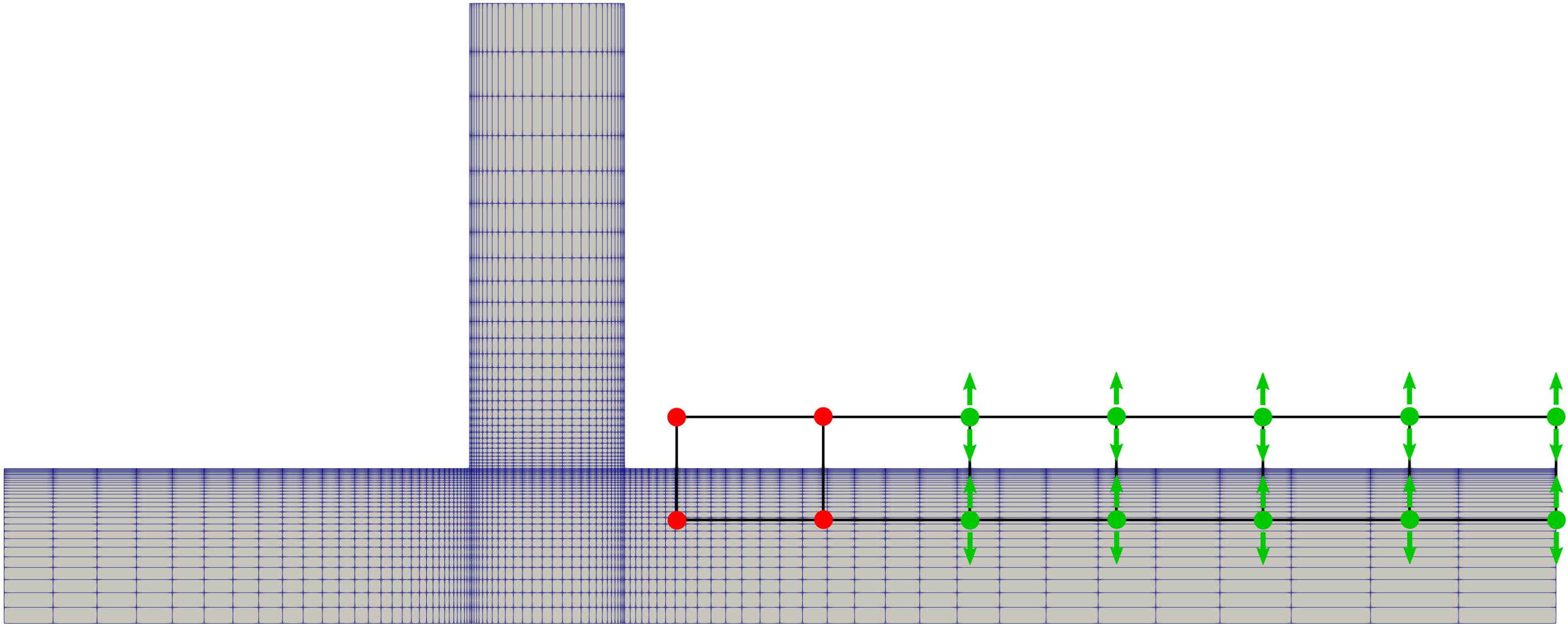 Figure (1): FFD-Box with fixed points (red) and allowed deformation direction indicated by arrows.
3. Mesh deformation test
Before attempting a gradient validation or optimization it is good practice to check whether the mesh deformation process creates valid and good quality meshes. It is also possible to already check reasonable preliminary bounds for FFD values, that can be set in an optimization. This can be done in a manual process which is rather simple.
First, some general FFD-Box deformation parameters. Additions are FFD_TOLERANCE, FFD_ITERATIONS and FFD_CONTINUITY which was set to USER_INPUT in order to not fix any points at all. With that option one can manually fix FFD-Box points using FFD_FIX_I/J/K options but this process can also be done without that options as will be shown below.
% -------------------- FREE-FORM DEFORMATION PARAMETERS -----------------------%
%
% Tolerance of the Free-Form Deformation point inversion
FFD_TOLERANCE= 1E-10
%
% Maximum number of iterations in the Free-Form Deformation point inversion
FFD_ITERATIONS= 500
%
% FFD box definition: 3D case (FFD_BoxTag, X1, Y1, Z1, X2, Y2, Z2, X3, Y3, Z3, X4, Y4, Z4,
%                              X5, Y5, Z5, X6, Y6, Z6, X7, Y7, Z7, X8, Y8, Z8)
%                     2D case (FFD_BoxTag, X1, Y1, 0.0, X2, Y2, 0.0, X3, Y3, 0.0, X4, Y4, 0.0,
%                              0.0, 0.0, 0.0, 0.0, 0.0, 0.0, 0.0, 0.0, 0.0, 0.0, 0.0, 0.0)
% Start at the lowest leftest corner and turn counter-clockwise
FFD_DEFINITION= (BOX, \
0.065, 0.01, 0.0, \
0.15, 0.01, 0.0 \
0.15, 0.02, 0.0, \
0.065, 0.02, 0.0, \
0.0, 0.0 ,0.0, \
0.0 ,0.0, 0.0, \
0.0, 0.0, 0.0, \
0.0, 0.0, 0.0 )
%
% FFD box degree: 3D case (i_degree, j_degree, k_degree)
%                 2D case (i_degree, j_degree, 0)
FFD_DEGREE= (6, 1, 0)
%
% Surface grid continuity at the intersection with the faces of the FFD boxes.
% To keep a particular level of surface continuity, SU2 automatically freezes the right
% number of control point planes (NO_DERIVATIVE, 1ST_DERIVATIVE, 2ND_DERIVATIVE, USER_INPUT)
FFD_CONTINUITY= USER_INPUT
%
% Definition of the FFD planes to be frozen in the FFD (x,y,z).
% Value from 0 FFD degree in that direction. Pick a value larger than degree if you don't want to fix any plane.
%FFD_FIX_I= (0,2,3)
%FFD_FIX_J= (0,2,3)
%FFD_FIX_K= (0,2,3)
The next set of option changes DV_KIND, DV_PARAM and DV_VALUE have to be specified for each Design Variable. So each of those options must have the same number of entries.
For DV_KIND the tag FFD_CONTROL_POINT_2D is simply repeated 10 times.
The DV_PARAM option lists, which of the FFD-Box points is going to be deformed and also the direction of deformation. So (BOX, 2, 0, 0.0, 1.0) refers to a point in the FFD-Box names BOX with the i-j-indices 2, 0 and will be deformed along the vector 0.0, 1.0 i.e. in y-direction. In 3D, this is of course extended by k-indices and the z-axis.
The DV_PARAM list can either be created by hand or by editing the output of a helping script that ships with SU2 (same directory as SU2_CFD binary etc.):
$ python set_ffd_design_var.py -i 6 -j 1 -k 0 -b BOX -m 'wall' --dimension 2
which creates these list for the FFD_CONTROL_POINT_2D’s in x-y-z direction, but we are only interested in the y-direction.
% FFD_CONTROL_POINT_2D (Y)
DEFINITION_DV= ( 19, 1.0 | wall | BOX, 0, 0, 0.0, 1.0 ); ( 19, 1.0 | wall | BOX, 1, 0, 0.0, 1.0 ); ( 19, 1.0 | wall | BOX, 2, 0, 0.0, 1.0 ); ( 19, 1.0 | wall | BOX, 3, 0, 0.0, 1.0 ); ( 19, 1.0 | wall | BOX, 4, 0, 0.0, 1.0 ); ( 19, 1.0 | wall | BOX, 5, 0, 0.0, 1.0 ); ( 19, 1.0 | wall | BOX, 6, 0, 0.0, 1.0 ); ( 19, 1.0 | wall | BOX, 0, 1, 0.0, 1.0 ); ( 19, 1.0 | wall | BOX, 1, 1, 0.0, 1.0 ); ( 19, 1.0 | wall | BOX, 2, 1, 0.0, 1.0 ); ( 19, 1.0 | wall | BOX, 3, 1, 0.0, 1.0 ); ( 19, 1.0 | wall | BOX, 4, 1, 0.0, 1.0 ); ( 19, 1.0 | wall | BOX, 5, 1, 0.0, 1.0 ); ( 19, 1.0 | wall | BOX, 6, 1, 0.0, 1.0 )
Now in order to get the DV_PARAM list simply the first part of each entry, namely 11, 1.0 | wall | has to be deleted.
Here the user can also fix certain Design variables by simply not using them in the lists. Note how in the given DV_PARAM the first point is (BOX, 2, 0, 0, 0.0, 1.0, 0.0 ) instead of (BOX, 0, 0, 0, 0.0, 1.0, 0.0 ). Like so. The first two points with the lowest i-index are fixed.
DV_Value simply gives the Deformation of the respective Design Variable. If in DV_PARAM only unit vectors are given as deformation direction (which is the case as we only use 0.0, 1.0, 0.0) then DV_VALUE is the deflection in [m] and therefore some intuition can be used when choosing testing values.
% ----------------------- DESIGN VARIABLE PARAMETERS --------------------------%
%
DV_KIND= FFD_CONTROL_POINT_2D, FFD_CONTROL_POINT_2D, FFD_CONTROL_POINT_2D, FFD_CONTROL_POINT_2D, FFD_CONTROL_POINT_2D, FFD_CONTROL_POINT_2D, FFD_CONTROL_POINT_2D, FFD_CONTROL_POINT_2D, FFD_CONTROL_POINT_2D, FFD_CONTROL_POINT_2D
%
% Marker of the surface in which we are going apply the shape deformation
% NOTE: for deformation the outlet should be a MARKER_SYM to hinder the mesh being ripped apart.
DV_MARKER= ( wall )
%
% Parameters of the shape deformation
% - FFD_SETTING ( 1.0 )
% - FFD_CONTROL_POINT ( FFD_BoxTag, i_Ind, j_Ind, k_Ind, x_Disp, y_Disp, z_Disp )
DV_PARAM= (BOX, 2, 0, 0.0, 1.0); (BOX, 3, 0, 0.0, 1.0); (BOX, 4, 0, 0.0, 1.0); (BOX, 5, 0, 0.0, 1.0); (BOX, 6, 0, 0.0, 1.0);  (BOX, 2, 1, 0.0, 1.0); (BOX, 3, 1, 0.0, 1.0); (BOX, 4, 1, 0.0, 1.0); (BOX, 5, 1, 0.0, 1.0); (BOX, 6, 1, 0.0, 1.0)
% Excluded FFD points that are fixed to keep a nice geometry and mesh
%DV_PARAM= (BOX, 0, 0, 0.0, 1.0); (BOX, 1, 0, 0.0, 1.0); (BOX, 0, 1, 0.0, 1.0); (BOX, 1, 1, 0.0, 1.0);
%
% Value of the shape deformation
% first row:  lower row y-direction
% second row: upper row y-direction
DV_VALUE= 0.003, 0.003, 0.004, 0.005, 0.005, \
          0.003, 0.003, 0.004, 0.005, 0.005
The most important options for the volume mesh algorithm are listed below. This tutorial does not go in depth on these options.
% ------------------------ GRID DEFORMATION PARAMETERS ------------------------%
%
% Linear solver or smoother for implicit formulations (FGMRES, RESTARTED_FGMRES, BCGSTAB)
DEFORM_LINEAR_SOLVER= FGMRES
%
% Preconditioner of the Krylov linear solver (ILU, LU_SGS, JACOBI)
DEFORM_LINEAR_SOLVER_PREC= ILU
%
% Number of smoothing iterations for mesh deformation
DEFORM_LINEAR_SOLVER_ITER= 1000
%
% Number of nonlinear deformation iterations (surface deformation increments)
DEFORM_NONLINEAR_ITER= 1
%
% Minimum residual criteria for the linear solver convergence of grid deformation
DEFORM_LINEAR_SOLVER_ERROR= 1E-14
%
% Print the residuals during mesh deformation to the console (YES, NO)
DEFORM_CONSOLE_OUTPUT= YES
%
% Deformation coefficient (linear elasticity limits from -1.0 to 0.5, a larger
% value is also possible)
DEFORM_COEFF = 0.0
%
% Type of element stiffness imposed for FEA mesh deformation (INVERSE_VOLUME,
%                                           WALL_DISTANCE, CONSTANT_STIFFNESS)
DEFORM_STIFFNESS_TYPE= WALL_DISTANCE
%
% Deform the grid only close to the surface. It is possible to specify how much
% of the volumetric grid is going to be deformed in meters or inches (1E6 by default)
DEFORM_LIMIT = 1E6
This mesh deformation is executed via:
$ SU2_DEF <config-file>.cfg
In this special case the deformed produces a bad mesh at the outlet, as the mesh is ‘ripped apart’ there. This happens because the FFD-Box only deforms what is prescribed in DV_MARKER and the remaining boundaries are considered ‘clamped’ in the volume mesh algorithm. All boundaries? No! The boundaries in MARKER_SYM are allowed to move along their symmetry plane in the volume mesher.This obviously requires the boundary to form a single plane which is the case for the present outlet. So, if the outlet is prescribed as a MARKER_SYM for the Volume deformation step the mesh deformation will yield a reasonable mesh.
After the mesh deformation it is advisable to also run a primal simulation on that deformed mesh, as the simulation settings (e.g. CFL_NUMBER) might not lead to a converging simulation anymore. For a later optimization run this testing can help keeping a converging primal through all deformations.
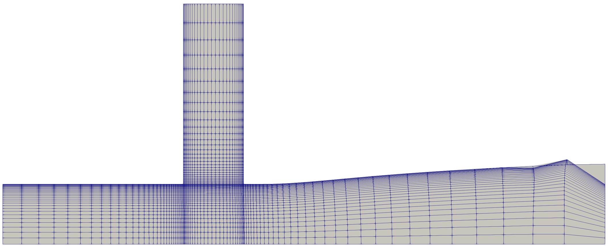 Figure (2): Mesh breaks at the
 outlet, as outlet nodes are clamped.
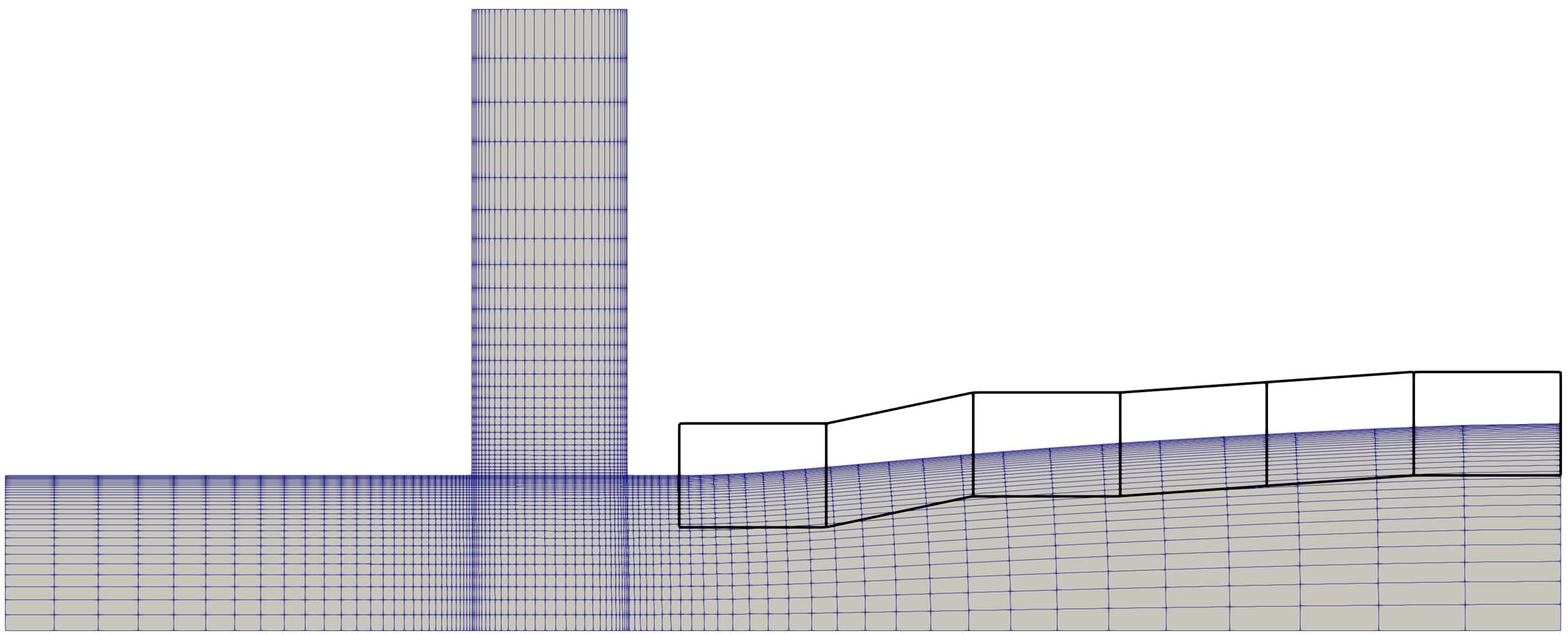 Figure (3): Defining the
 outlet as MARKER_SYM results in a satisfactory deformed mesh.
4. Gradient Validation
In the gradient validation the Discrete Adjoint gradient is compared against a Finite Difference gradient. The script gradient_validation.py is using FADO, so please make yourself familiar with the tutorials in that respective repository. But with the comments in the file and observing the output it is possible to reverse engineer many aspects.
Notable here is that, first, all deformed primal computations are done and the baseline at the very end. This is done as the discrete adjoint requires the solution of the baseline mesh, so that is done right before computing the discrete adjoint gradient.
The MARKER_SYM-trick that was introduced in the mesh-deformation section is also applied here and also in the SU2_DOT_AD step. This is required to stay consistent between the mesh deformation execution and the gradient projection.
The Objective Function used is SURFACE_SPECIES_VARIANCE and, as the name suggests, sums the local differences in the species mass fraction against the mean, and can therefore be used as a measure for uniform mixing. A Variance of zero would indicate perfect mixing.
The gradient validation script is executed via:
$ python gradient_validation.py
In order to postprocess the results a python script is added which compares both gradients and prints to screen and file:
$ python postprocess.py
At a maximum of ~0.05% relative difference between the discrete adjoint and finite difference gradient,the agreement is excellent.
+---+-------------------+-------------------+-------------------+-------------------+
| # |       DA gradient |       FD gradient |     absolute diff | relative diff [%] |
+---+-------------------+-------------------+-------------------+-------------------+
| 0 |     -0.0031128563 |     -0.0031137331 |      0.0000008768 |      0.0281680151 |
| 1 |     -0.0005406673 |     -0.0005409528 |      0.0000002856 |      0.0528178961 |
| 2 |      0.0011094759 |      0.0011093871 |      0.0000000888 |      0.0080034781 |
| 3 |      0.0017487956 |      0.0017487712 |      0.0000000245 |      0.0014009004 |
| 4 |      0.0017256761 |      0.0017256695 |      0.0000000066 |      0.0003839967 |
| 5 |     -0.0031128563 |     -0.0031137331 |      0.0000008769 |      0.0281689729 |
| 6 |     -0.0005406673 |     -0.0005409528 |      0.0000002855 |      0.0528118802 |
| 7 |      0.0011094759 |      0.0011093871 |      0.0000000888 |      0.0080064097 |
| 8 |      0.0017487956 |      0.0017487711 |      0.0000000246 |      0.0014043103 |
| 9 |      0.0017256761 |      0.0017256695 |      0.0000000066 |      0.0003847820 |
+---+-------------------+-------------------+-------------------+-------------------+
5. Optimization
The setup of a shape optimization with FADO is rather straight forward once a working gradient validation script is available. It is usually a good idea to add lower and upper bounds to the design variables. In the case of FFD-Box points these values translate directly into the cartesian space and a first estimation can be made intuitively.
The second notable extension to the gradient validation is of course the optimization setup itself. Please follow the tutorials FADO provides to learn more about the capabilities and options. But, in the provided script some additional explanations are given and more details to certain function can be printed to screen by adding e.g. printDocumentation(driver.setFailureMode) to the script if more information for that option are required.
The optimization method used is SLSQP from the SciPy library.
The unconstrained optimization with the objective function of SURFACE_SPECIES_VARIANCE (as in the gradient validation introduced) is started with the following command:
$ python optimization.py
In order to compute the gradient norms of each Design iteration a gradient_norm.py script was added. The script will write a gradient_norm.csv into the folder root which.
A helpful visualization after an optimization run is having the series of deformed meshes with their primal solution and FFD-Boxes. These solution are in their respective folders and one could tediously load every single one of them.
The script create_Visu_symlinks.py sweeps through the DSN_* folders and collects symbolic links of the primal solution and FFD-Boxes into a visu_files folder. The symbolic links also renames each file and appends an iteration number to the end of the filename (e.g. ffd_004.vtk -> ../DSN_004/DEFORM/ffd_boxes_def_0.vtk). Like so, this data can be loaded in Paraview, or probably any other post-processor, as a time series which allows for easy cycling through the designs.
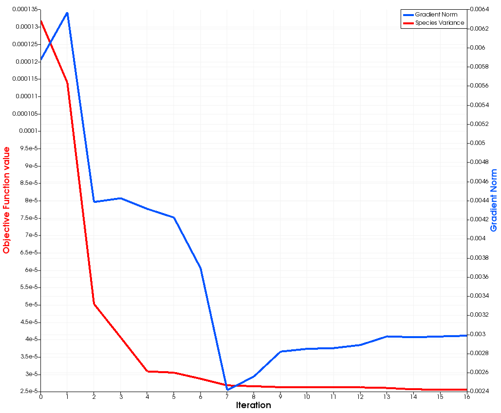 Figure (4): Objective Function value and Gradient Norm over optimizer iterations. Capped after 12 iterations.
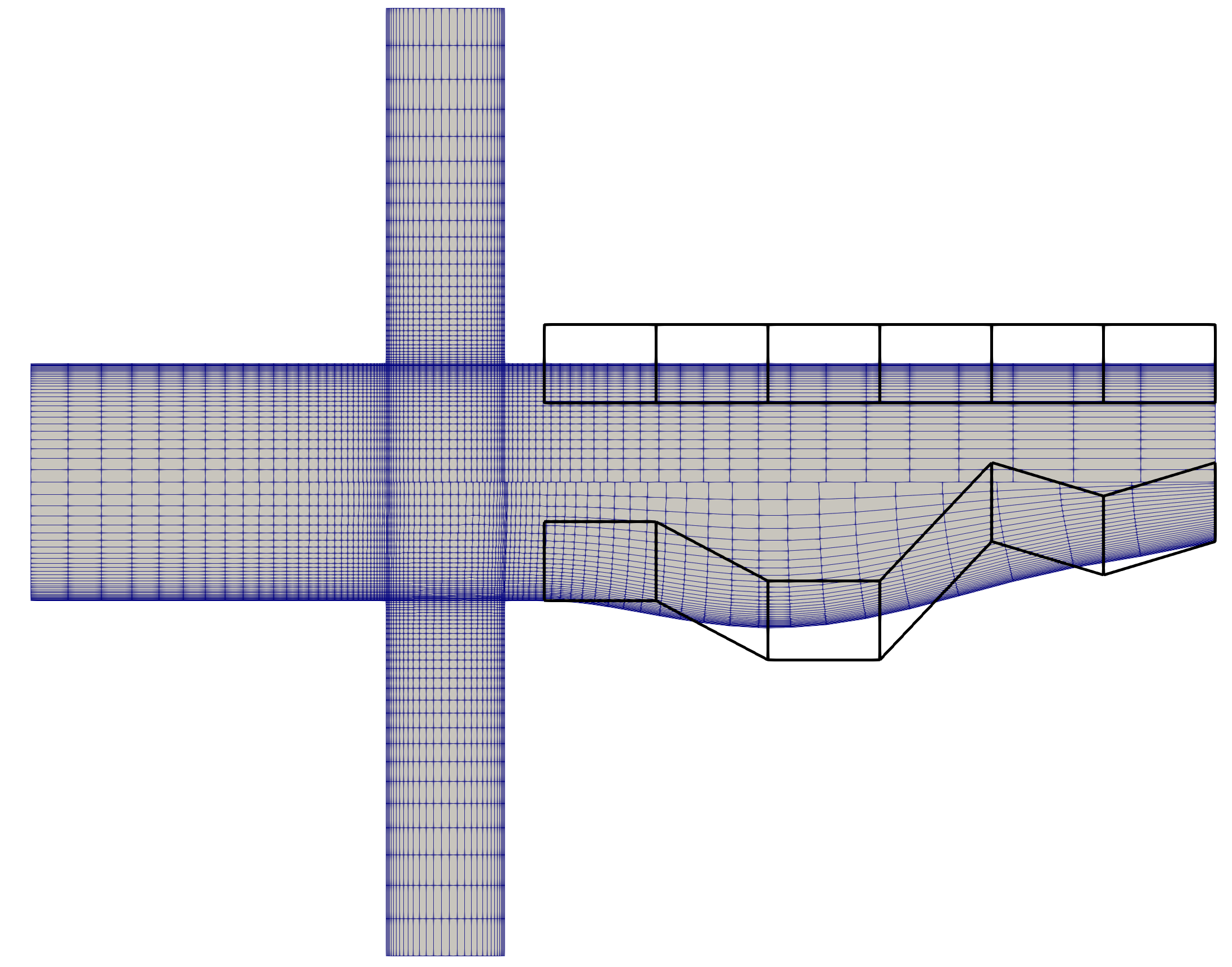 Figure (5): Baseline and Optimized Mesh with the respective FFD-Boxes.
 Figure (6): Optimization series from baseline to final mesh with FFD-Boxes.